Volcanoes VS Atmospheric CO2 As Global Heat Source
As I am pressed for time I prepared the following diagrams on a white board free-hand instead of using my drafting board or out of date flow charting software, all of wwhich
allow one to draw straight lines. I used color arrows to show the direction of electron flow through the circuits. Below is a schematic of the power supply in its 10 volt half wave mode when the
electron flow in the power transformer's primary coil is travelling upwards. When the primary's electron flow is travelling downwards diode D2 will block the flow irregardless of which position switch S3 is in.
When slider switch, S2, is in its other position for 20 volt operation, we see the change in electron flow below:
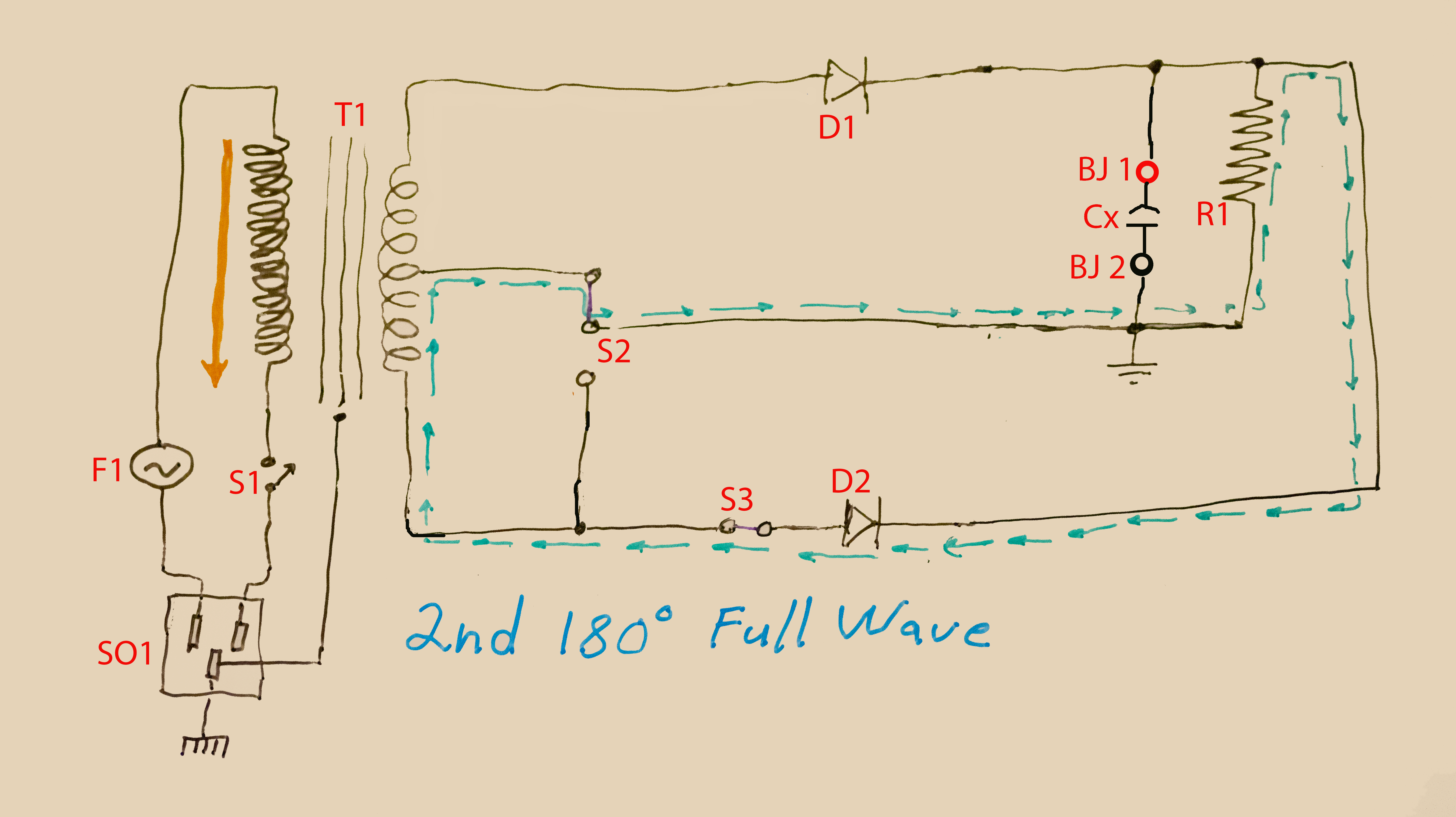
Full wave operation is available by leaving switch S2 in its 10 volt position and closing switch S3. Here is the electron flow in the circuit when the electron flow
in in the primary coil is upwards bound.
Here is the change in the circuit's electron flow when the electron flow in the primary coil reverses its direction. This takes place 60 times a second here in North America:
Although I mounted all my circuit components on a piece of plexiglass, I connected the power transformer's metal frame to the Earth Ground in the 3 prong AC Receptical
SO1.
To repeat my demo, you don't need anything as elaborate as these two devices. An AC cord with a few Mar connectors could be used with a power transformer, a rectifier
diode, set of electrolytic capacitors, a suitable power resistor, and a bunch of clip leads,- will suffice as long as you know and follow the safety precautions to take when working with
electricity.
You also don't need a triggered sweep 100 Mhz dual trace oscilloscope, as a surplus 5 or 10 Mhz single trace oscilloscope will do the job with a little extra work.
Even a 1 Mhz single trace scope would do if available even as surplus.