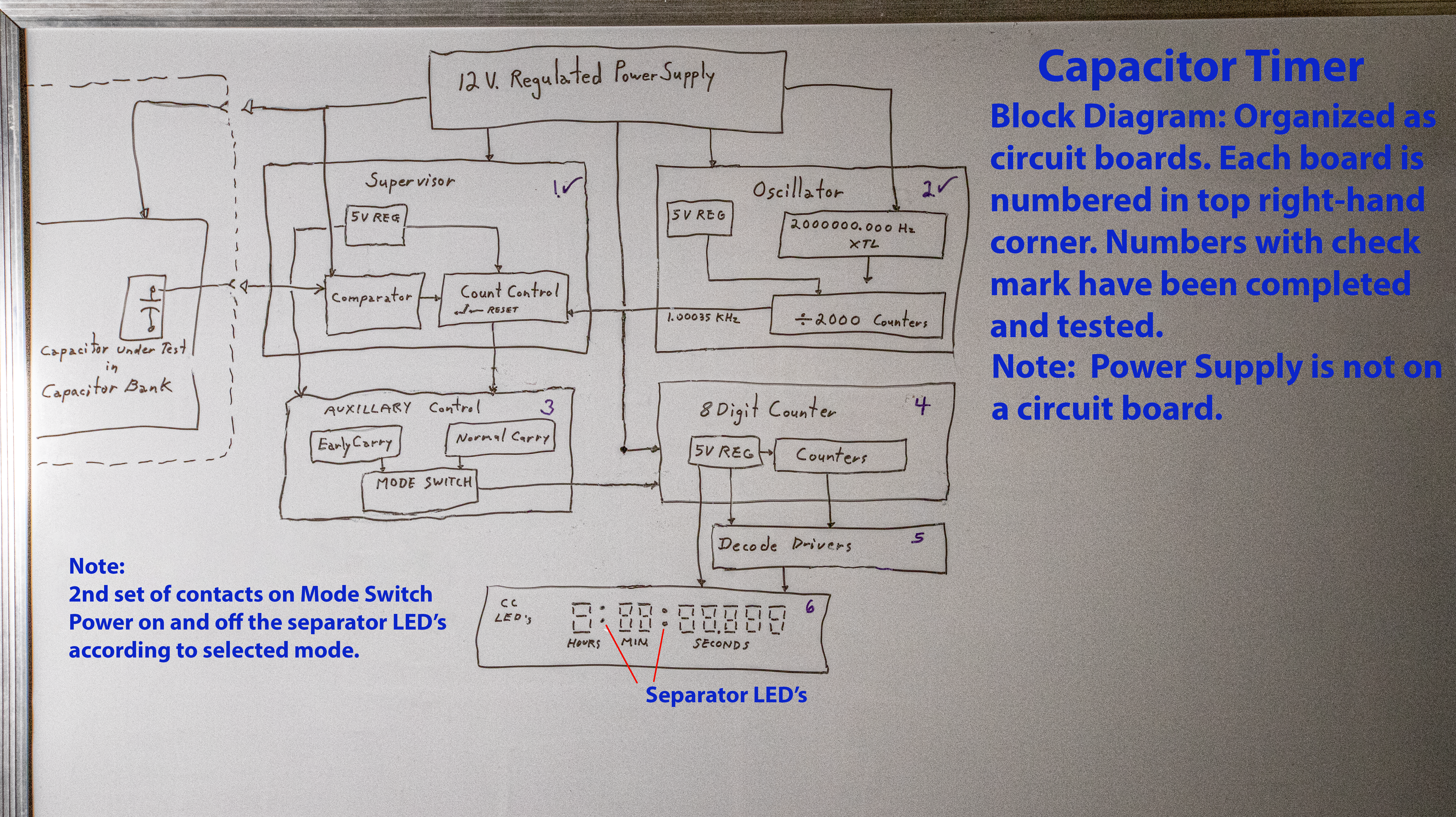
As with all my previous circuit drawings, I have drawn it free hand on a white board. This allows me to
make rapid changes as I develope my ideas. It also is a very powerful tool along with the bread-board that allows me to test the changes I think of. You
have already seen photos and videos of my bread-boarded circuits in action. I completed the final Oscillator board first, and connected it to my timer's
breadboard in place of the breadboarded crystal controlled oscillator.
The crystal used in my final hard wired oscillator was not as accurate as the one in my breadboarded oscillator:
instead of giving me 2.00014 MHz dividing down to 1.00007 Mhz it gave me 2.00065 MHz, which divided down to a measured 1.00035 KHz. The 70 microsecond error could be ignored, but the 350 microsecond
error is too large for that. I will have to add a CD4046B CMOS Phased Lock Loop IC with its Low Pass Filtering to clean up this signal.
Here the PLL's low pass filter eliminates the erroneous high frequencies of the crystal's oscillations. While the crystal
is stamped 2.0000 Mhz, the fifth and sixth digits that yeild 2.0000xx are not stable, making the fourth digit unreliable as well. Thus the crystal is only accurate to three
places. ie. 2.000 Mhz. The digits beyond the third place mark "microseconds" and thus are a higher frequency component of the crystal's oscillations. The Phase
Locked Loop's low frequency filter eliminates this higher frequency component, maintaining the crystal's three place accuracy down to a single millisecond. Below is a labled
photograph of my wired oscillator.

I powered the breadboarded oscillator from a separate 18 Volt power supply in the belief that a higher voltage was required to shock
the crystal into its oscillations. In testing my wired oscillator with my bench supply, I found it would continue to oscillate with a voltage supply of only 6 volts, and could
be shocked into oscillation from the same 12 Volts I used for the Supervisor Board's voltage comparator. This simplifies my Capacitor Timer by reducing the number of different
voltages required for it to operate properly.
As expected, the shorter circuit board traces and lead dress of my hard wired circuit, along with the use of bypass capacitors,- eliminated the noise
seen in my breadboarded version. The following video clip shows how the hard wired version is much improved over the breadboarded version.
When I recieve the CD4046B Phase Locked Loop IC's I have on order, and added one to my wired oscillator board, my oscillator will deliver
a stable stream of clean and accurate 1 millisecond pulses for my Capacitor Timer to count.
Unfortunately, I would have to multiply the frequency of my phase Locked Loop's Voltage Controlled Oscilator by 100,000 in order to make the extra
350 microseconds appear large enough for the Loop's Low Pass Filter to filter out. This would require 5 decade counters in the feedback loop, and 5 more decade counters to bring the VCO's
output back down to the desired 1.000000 khz. That's a lot of circuit board real estate I can't afford.
Since the current 1.00035 Khz has a period of 0.999650 milliseconds which is 99.965% of the desired 1 millisecond, and there are time constraints on
the completion of my movie, I shall regard this 99.965% as not too shabby, and move on to the construction of the rest of this Capacitor Timer.
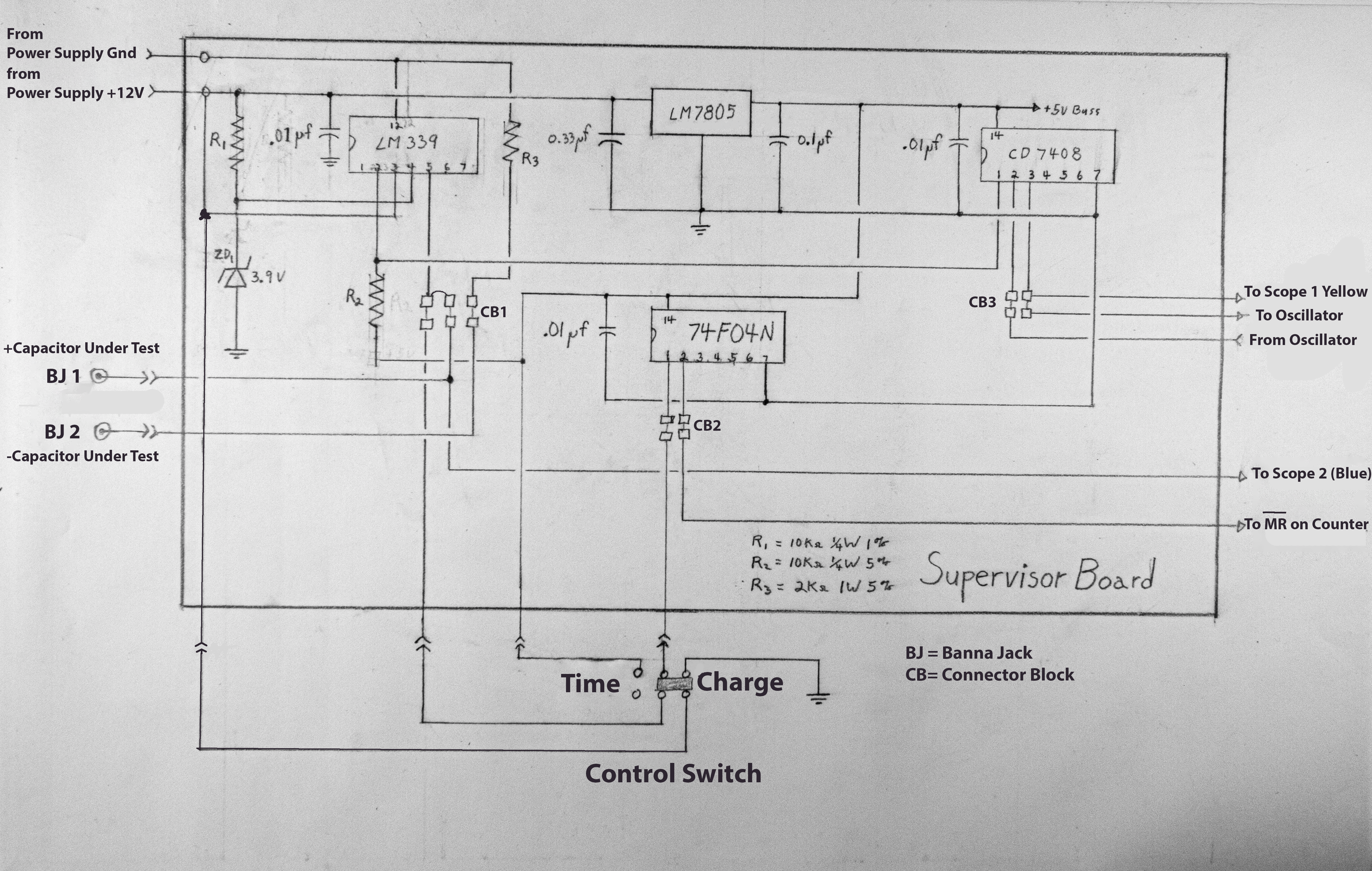
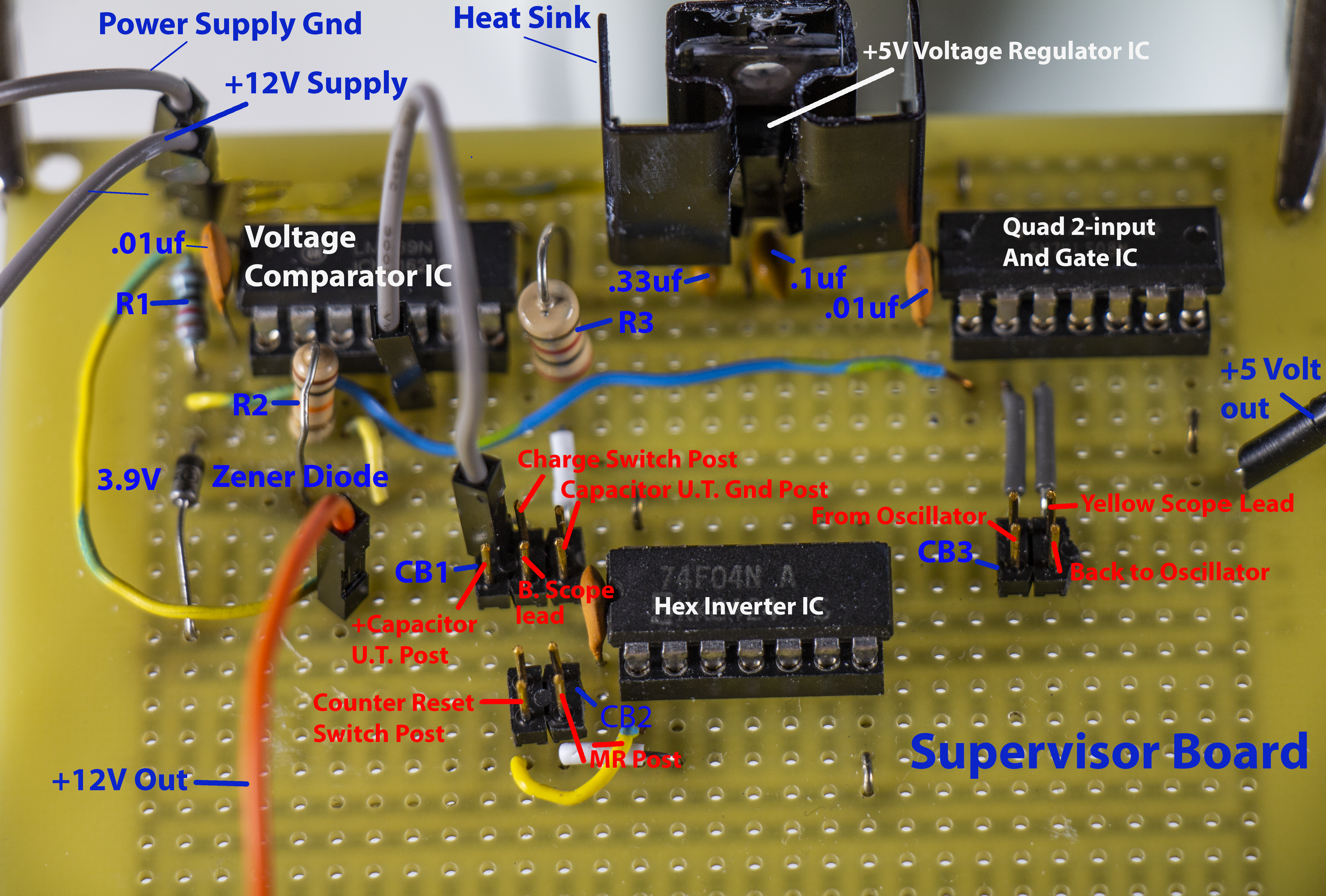
Next I completed the hard-wired Supervisor Board with a couple of minor changes. In place of the 2.7KΩ resistor
I used a 2.0KΩ resistor and I put a heat sink on the LM7805 voltage regulator IC. With its many connecting posts the Supervisor Board looks like a porcupine, so I drew the following
circuit schematic diagram to help you identify all the connections.
The calculated time for this circuit using a 1000 µf capacitor is:
Out of 15 trials the mean count obtained using the hard-wired oscillator together with the hard-wired supervisor and the 1000 µf capacitor was 4.221 seconds which is 6.1% too short. This is much better than being 15% or even 12.7% too long. Below is a photo of the Wired-Supervisor Board:
Below is the "Early Carry" and "Mode Enhancement" circuits put together as a single circuit to be wired on a third board as the "Auxillary Controller". When the mode switch at the top right is in the position shown, - the Early Carry signal is transmitted through the AND Gate to the Or Gate that applies the carry signal to the next counter. In the other position, the Early Carry signal is blocked by the And Gate so that only the Normal Carry signal passes through the Or Gate to the next counter. As both carry signals occur at different times there is no need for Exclusive Or Gates here. Since the 74LS192 decade counter IC's are on a separate board, there are only three IC's on the Auxillary Controller board, - with multiple connector blocks for the connections to and from the counter board.
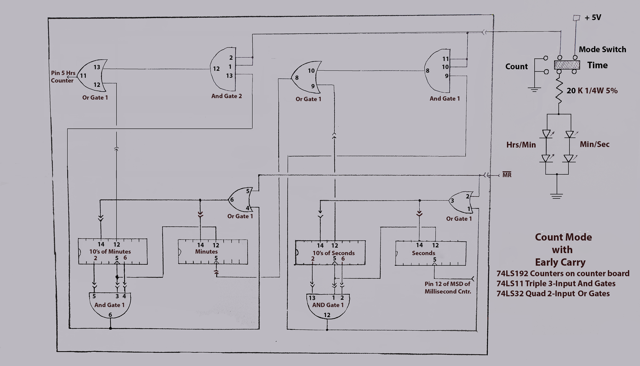
Note: I used a second 74LS11 Triple 3-Input And Gate IC to provide for the fourth And Gate where A simple 74LS08 2-Input And Gate IC would do, as it would give me two extra 3-Input And Gates that could be used to expand the Early Carry system to include the transition from hours to days. Not shown is the Auxillary Controller Board's 5 volt regulator that applies +5V to pin 14 of the all the logic Gate IC's with pin 7 serving as their grounds. The counter IC's get their +5V on pin 16 and their grounds on pin 8 from this regulator through additional connector blocks. The Mode switch is mounted on the rear panel of the enclosure, and the Separator LED's are mounted on the Display panel.