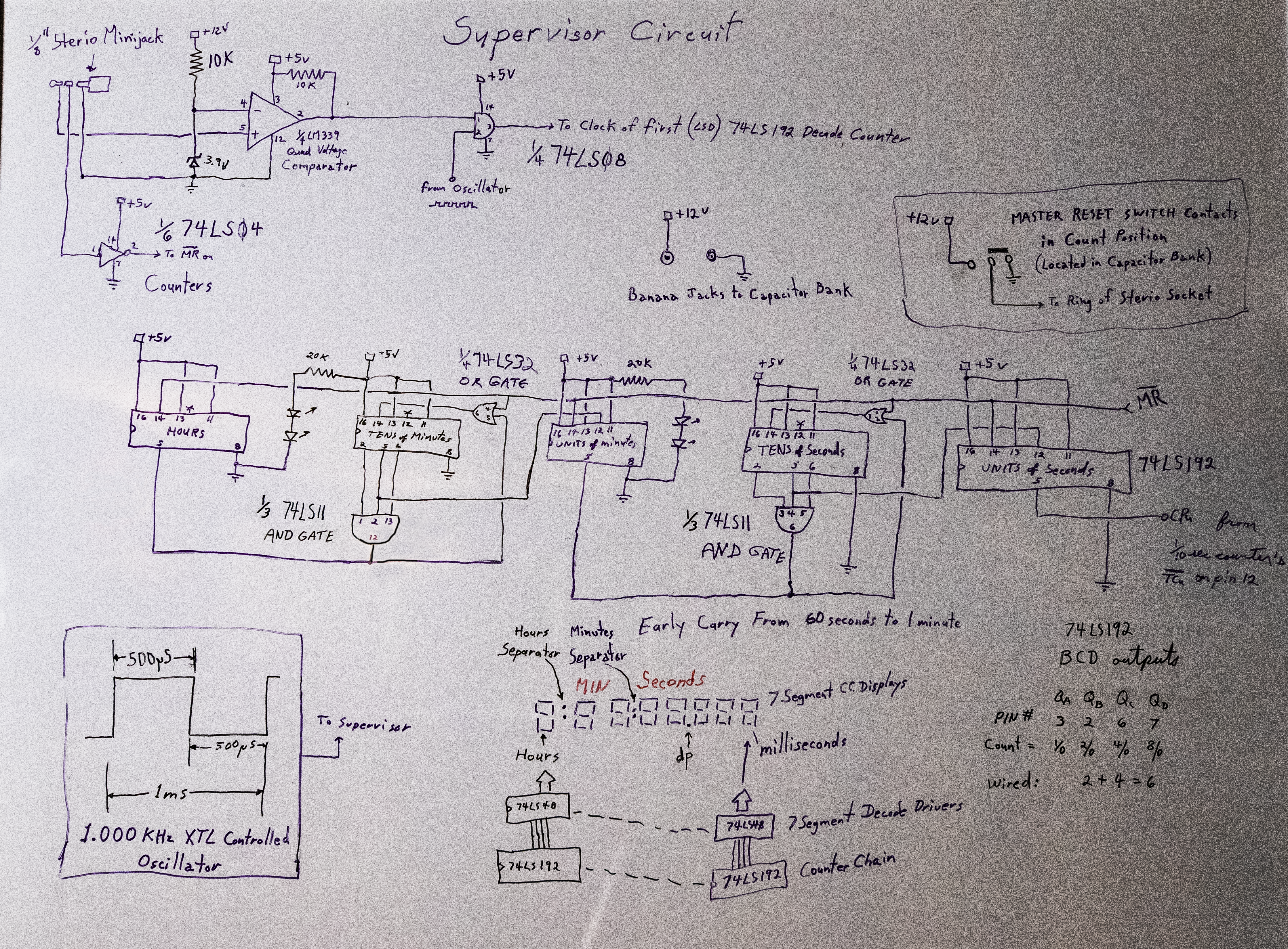
I am currently experimenting with varius crystal controlled oscillators to make an oscillator that will remain stable for days of continuous operation. The rest of the circuit is pretty straight forward: the voltage of the capacitor under test is fed to the non-inverting (+) input of an LM339 Quad Voltage Comparator IC. A set trip point provided by a 3.9 volt zener diode is applied to the comparator's inverting (-) input. As the capacitor discharges, its voltage falls exponentially. While the falling voltage remains above the trip-point the comparator's output will be held at a high logic level. This high logic level is fed to one of the inputs of an SN74LS08N Quad 2-input AND Gate IC, keeping this input to the And Gate high. The 1 milisecond pulses fed to the other input of the AND Gate will pass through to the AND Gate's output which feeds the clock pin of the least significant digit's counter in the counter chain.
When the capacitor's voltage falls below the trip-point, the Comparator's output will go "LOW" taking the input to the AND Gate "LOW" as well. This blocks the pulse stream from passing through the AND Gate, therebye stopping the count. The attained count will remain in the display until the counter is reset by putting the Capacitor Bank's "Charge/Discharge" switch in its charging position.
Here is a rough schematic diagram of the above system:
The formula for this circuit's Time in seconds is:
Where:
ET = Comparator's Trip-Point voltage = 3.9V.
EC = Capacitor's fully charged voltage = 12V.
Discharging the 68,000.0µf capacitor through a 2.7KΩ resistor yields:
Replacing this with a 2.2µf capacitor yeilds:
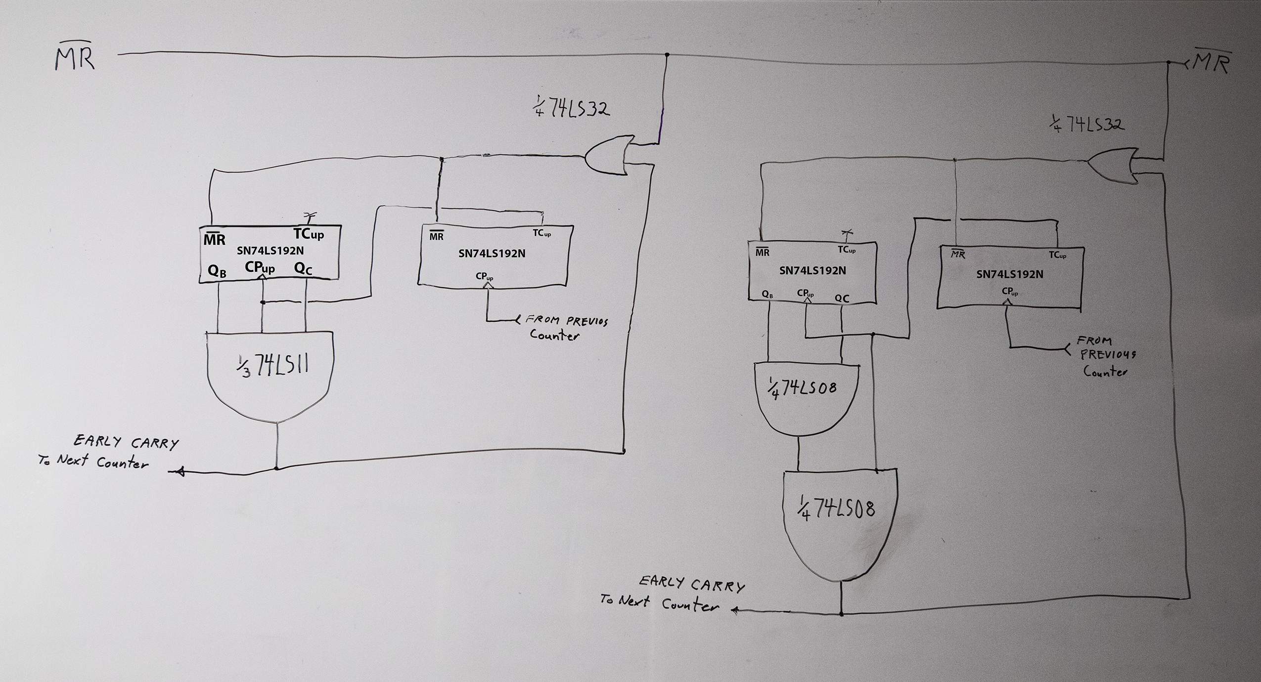
In generating an early carry pulse such as when 60 seconds = 1 minute, 60 minutes = 1 Hour, 24 hours = 1 day,
and 365 days = 1 year,- you not only need to detect the appropriate BCD count output on the counter ICs, but also produce a clock pulse when the appropriate count is detected.
This is accomplished by ANDing the clock pulse that produced the appropriate count with the detector's output. The generated carry pulse should be used to
reset the particular counters that produced the desired count. The diagram below shows how this is done using either an SN74LS08N Quad 2-Input AND Gate
or an SN74LS11N Triple 3-Input AND Gate: In the case presented in the diagram, the desired count is 6,- which occurs when both the QB
and the QC BCD outputs are high in the Most Significant Digit of the counting pair.
I used Dual-in-line ICs throught this system, as for single use instruments, I have no reason to set my Lab up for surface mount technology.
Below is a screen capture of the system's supervisor circuit in action. The oscillator used for the 1 KHz pulse stream is a simple 555 astable multivibrator which is not as stable as the crystal oscillator to be used in my final instrument. I have labled the significant traces in this capture. The scope's yellow lead monitors the output action on pin #3 of the SN74LS08N AND Gate, while the blue lead monitors the capacitor under test's voltage:
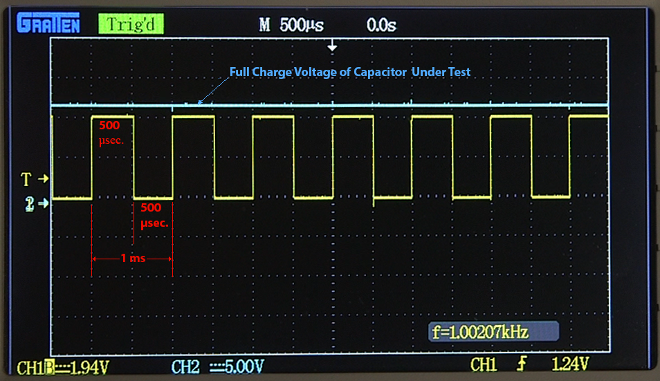
Please Note: The Red measurements are for a single pulse of which I adjusted the scope's Horizontal frequency to display a pulse train of 7 complete pulses (starting and ending on the falling edge of a pulse at both ends of the screen) making the actual screen dimension for what is indicated as 500µS only 1000/(7X2) = 71.42857143 or 71.4µS. Thus the scope's 500µS marking shows where the Falling edge of a single pulse would occur. The rising edge of that single pulse would have been at the left-hand edge of the scope's screen. Also note I set the scope's sweep trigger level to coincide with the circuit's trip-point voltage. The video below shows the Supervisor Circuit in action:
When finished, this instrument used with my Capacitor Bank, will accurately quantify the charge/discharge times of varius sized capacitors without boring my viewers with excessively long waits while the larger capacitors discharge.
Below is a photo of the bread-board version of this system used to produce the above Supervisor-in-action video:
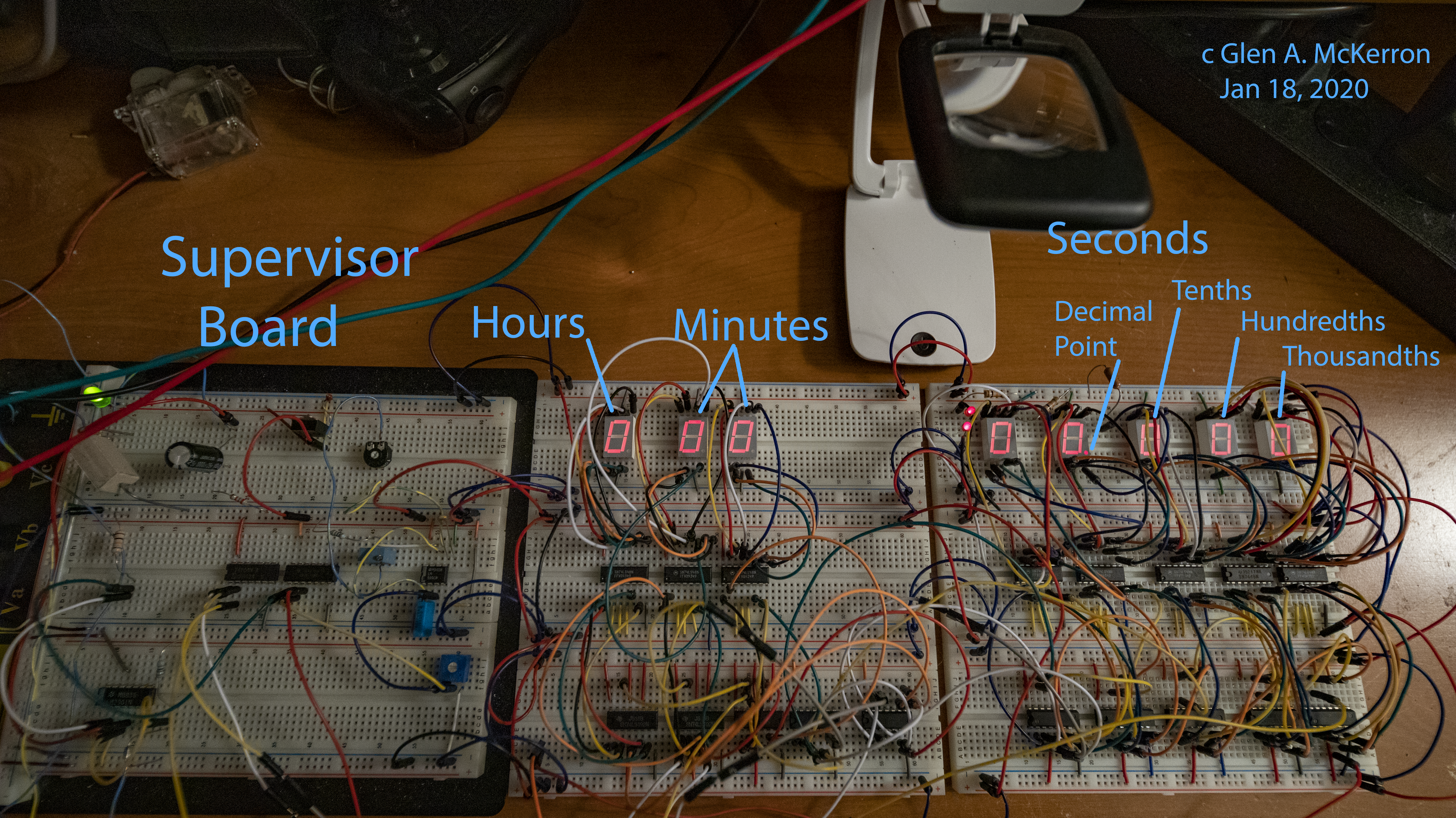
The capacitor under test
here was a 1000µf 50 Volt electrolytic capacitor. Here it was charged directly from the power supply's regulated 12.0 volts but discharged through
the circuit's 2.7KΩ resistor. Note how the chain of counting pulses at the AND Gate's output were cut off as the
falling capacitor voltage crossed the comparator's trip point. The counting chain will count only when both the Capacitor Bank's mode switch is set to "discharge",
and the discharge voltage is above the comparator's trip-point. The calculated Time for this capacitor was 6.069222522 or 6.069 seconds.
Here is my video of the bread-board circuit generating the early carry pulses discussed above: As mentioned in
the video the Early Carry causes the circuit to advance from a count of 00:59.999 to 01:00.000 instead of to 00:60.000
Finally, the following multi-camera view of my breadboard circuit and oscilloscope,- shows the comparator's trip-point stopping the counter.
Using the above 1000µf capacitor with the 2.7KΩ resistor, having a calculated time of 6.069 seconds in a series of 15 test runs
gave a mean count of 7.313 seconds. Thus the circuit's time was 1- (6.069/7.313) = 17.01080268 or 17% too long. The culprit here
The scope-measured frequency of the oscillator was 1.003xxx Khz when it should have been 1.000000 Khz or a maximum of
Replacing my on board 555 oscillator with my commercial signal generator, I was able to feed the supervisor's AND Gate with a frequency of 1.000xxx Khz. Fifteen more trial
runs gave me a mean count of 7.170 seconds, making the circuit's time 1 - (6.069/7.170) = 15.35564854 or 15% too long.
My crystal controlled oscillator with a rock steady frequency of 1.00007 Khz after 15 test runs brought the mean count down to 6.954 seconds,- making the circuit's
time 1- (6.069/6.954) = 12.72648835 or 12.7% too long. In the land of diminishing returns, this is as close to the theoretical value as I am likely to get.
When finished, this "Discharge Timer" will cover a continuous range of discharge times from a few milliseconds to 9 hours, 59 minutes and 59.999 seconds.
is the oscillator frequency was too high.
1.000xxx Khz. which is why
I am designing a crystal controlled oscillator for this device.
This verifies I need a more accurate oscillator.